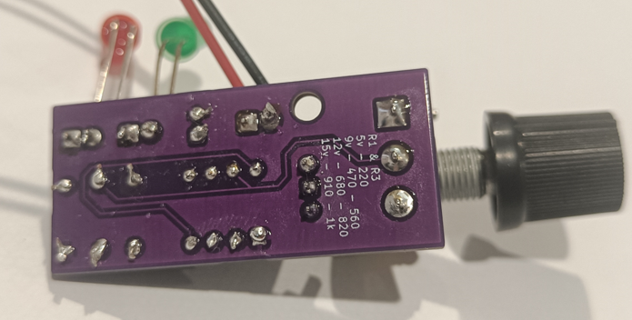
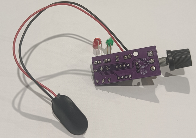
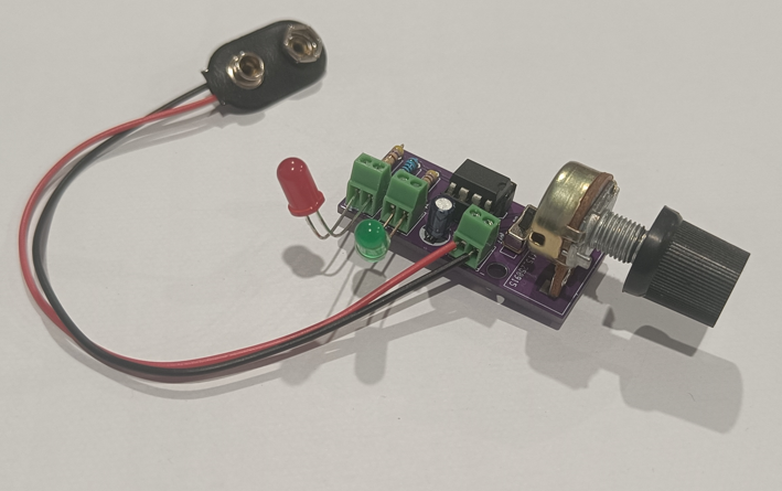
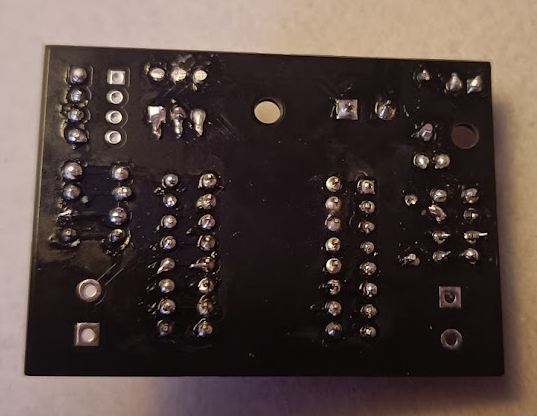
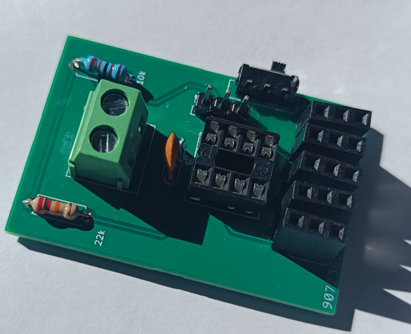
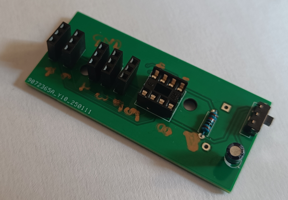
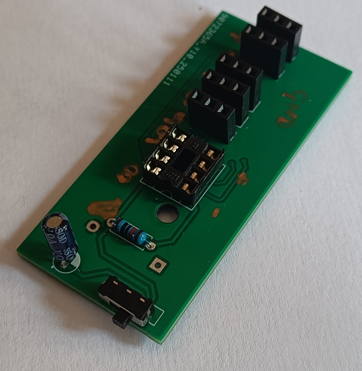
This was another small project, to continue my skills in PCB design, soldering and planning. I use silkscreening on the back to remind myself what different resistors to use for different input voltages.
Although this examples uses a 9v battery, the plan is to use it eventually on a model railway, which can use different voltages for different accessories.
Small Projects
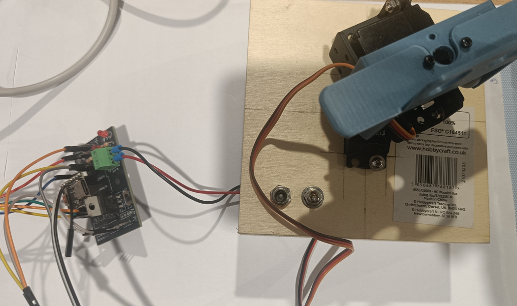
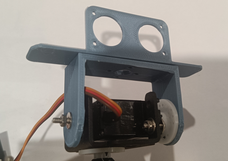
Pan / Tilt – ESP32
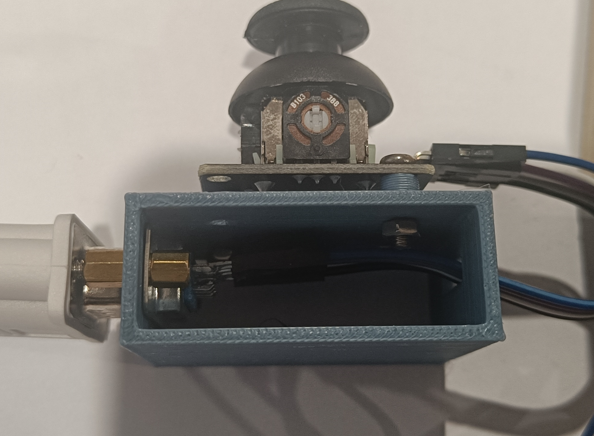
This design for a pan and tilt arrangement, was using a combination of different parts, some have been previously designed by myself. This uses the joystick to read analogue values and changes the position of the servo in relation to the position of the joystick.
– ESP32 Breakout Board (Previously Designed)
– 3D Printed Tilt Bracket and Joystick “housing”
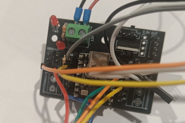
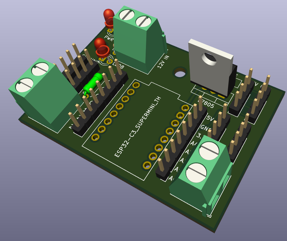
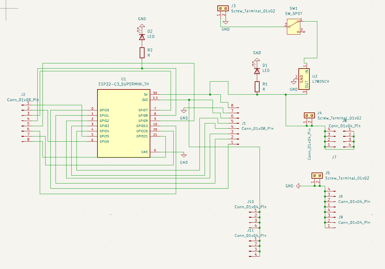
ESP32 – Breakout Board –
This project is expanding on my previous designs, learning from mistakes, including silkscreens and labeling the prototype board. This board has :
– 5v regulator, not only for the ESP32 but as a supply for connected components such as sensors.
– 3.3 v bus, directly linked to the 3.3v output of the ESP32
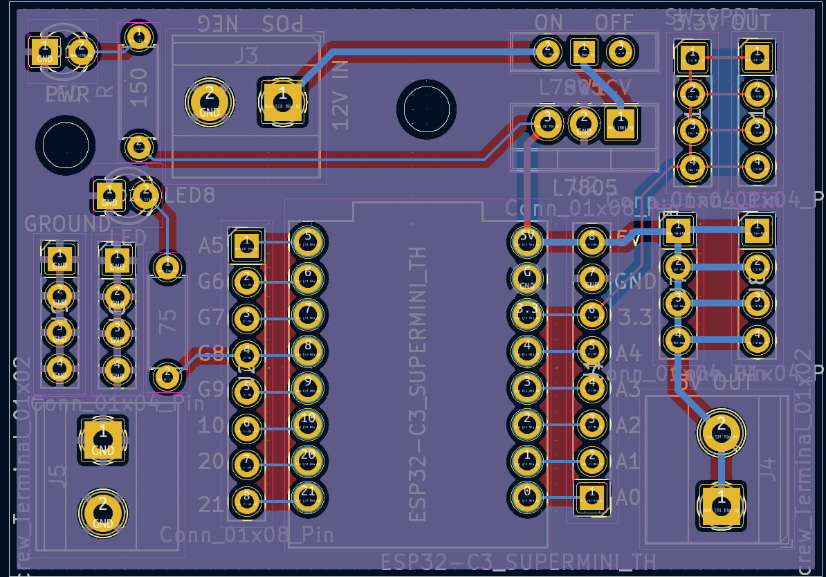
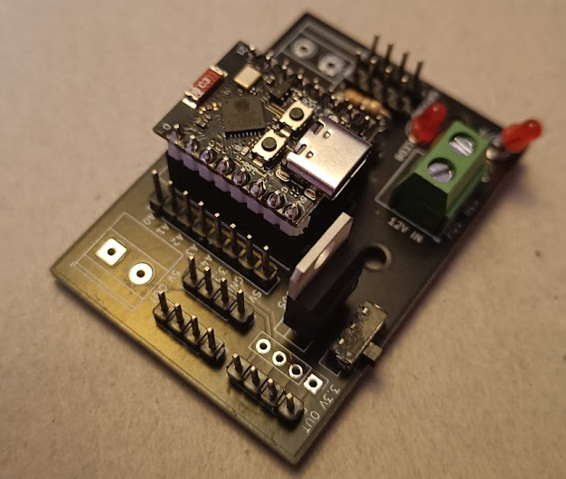
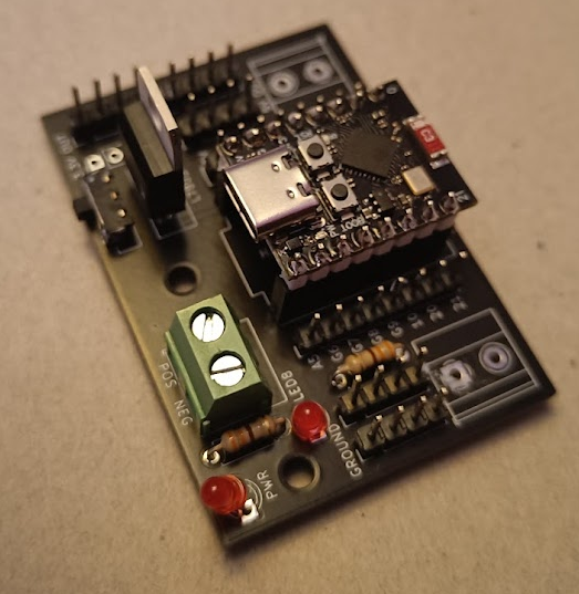
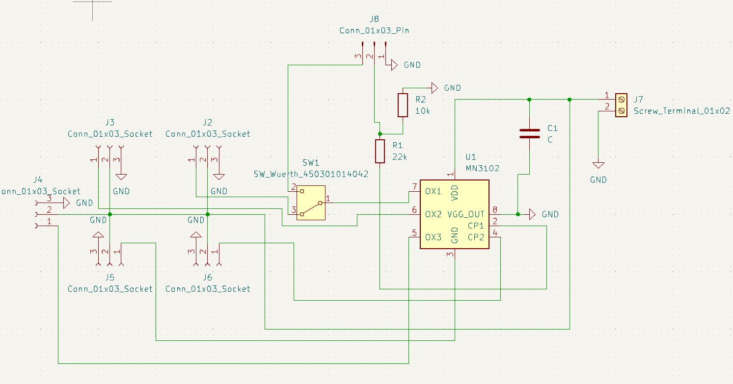
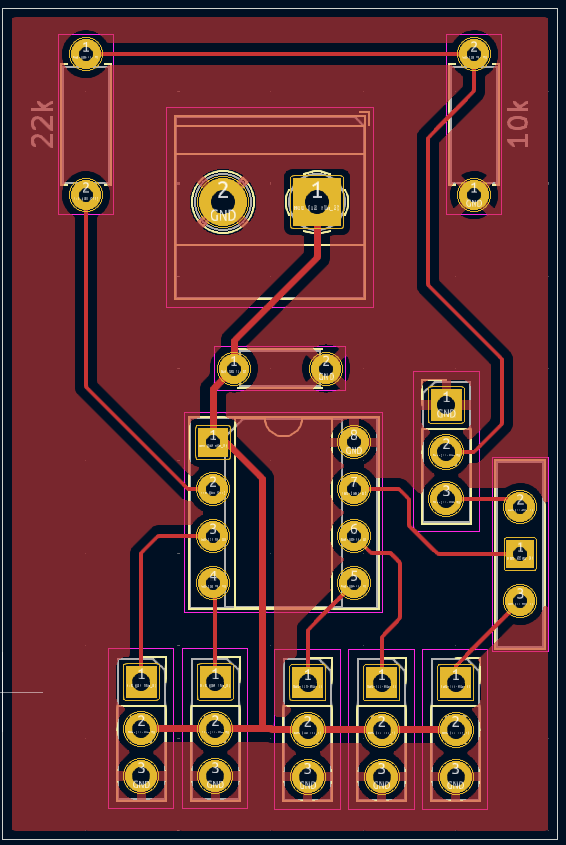
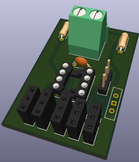
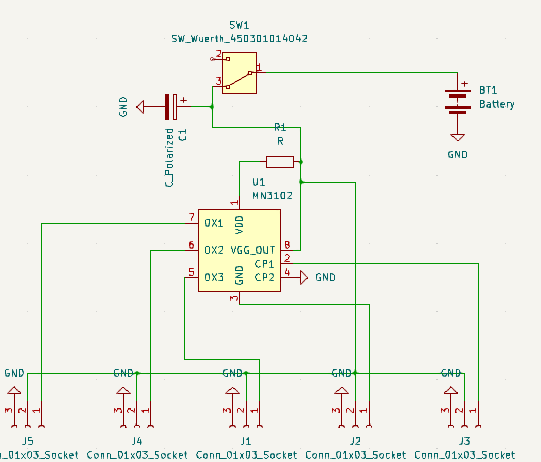
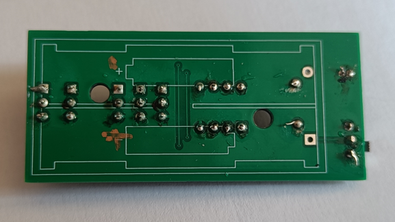
This was my first PCB Design, using the schematic given in there datasheets, i created a prototyping board, that had PCB Sockets for each pin out. There is a switch to allow one of the pins to change from a programming Pin (in) to a Pin (Out). This is a 1 layer board, all of the + and – pins are common.
This design was shipped out and the PCB was created by a 3rd party.
As with the other projects, the project went well however more labeling of what everything does needs be included on future project, such as max voltage, pin outs, resistor value etc.
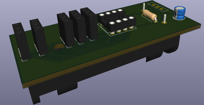
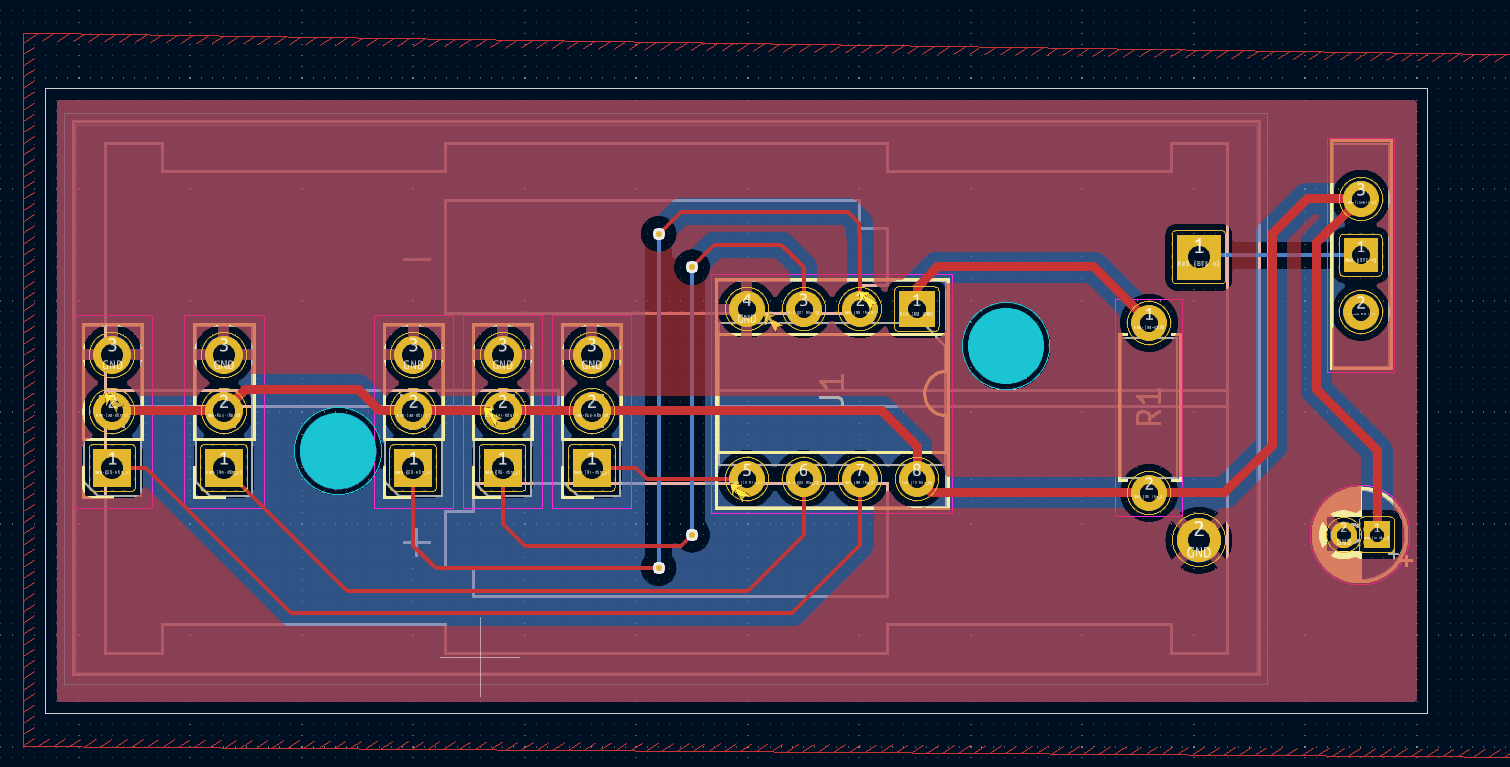
AT Tiny Board
This was a design to have easily connectable headers to be able to connect to an AT Tiny, such as the 45 or 85. This is a 2 layer board, that fits well with a 2 AA Battery holder to allow the project to run stand alone as the microchip can run at 3V. The Battery holder is on the opposite side of the board to make the footprint as small as possible. This design also use vias to allow for tracks to change layers.
This design was shipped out and the PCB was created by a 3rd party.
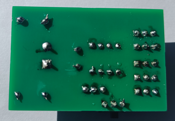
The project went well, the items all soldering in place with ease. Improvement, like with many of the other projects I have done, labeling of the PCB needs to be improved, in this case, what the + – S pins are , also what the pins are on the AT Tiny chip.