This project was to design and code a data logger that would “read” a few different sensors and record the results.
Project will Include:
Part Selection
PCB Design
Soldering
Arduino and Labview Code
Parts Used:
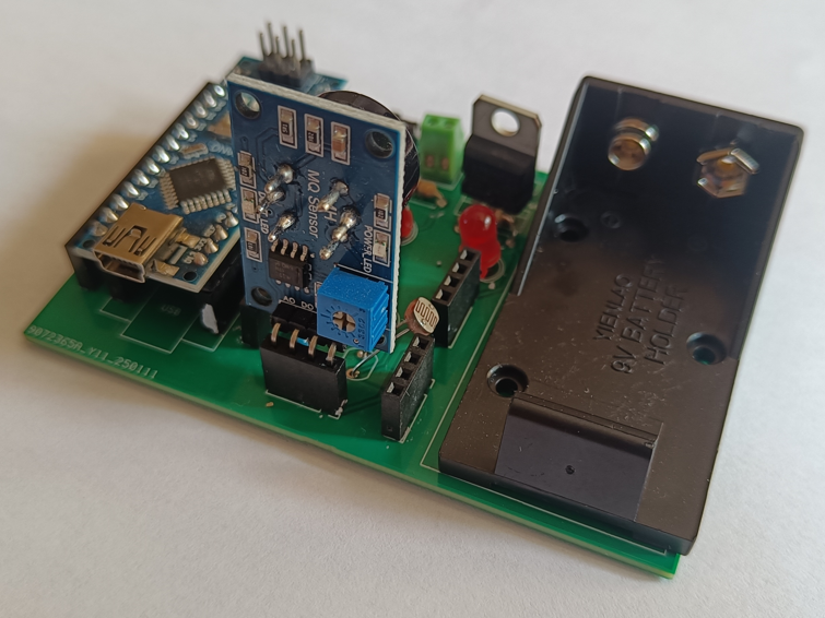
Arduino Nano
TMP 36 Temperature Sensor
5506 LDR
MQ-7 Carbon Monoxide Sensor
7805 Voltage Regulator
Breadboard / Prototype and Arduino Code
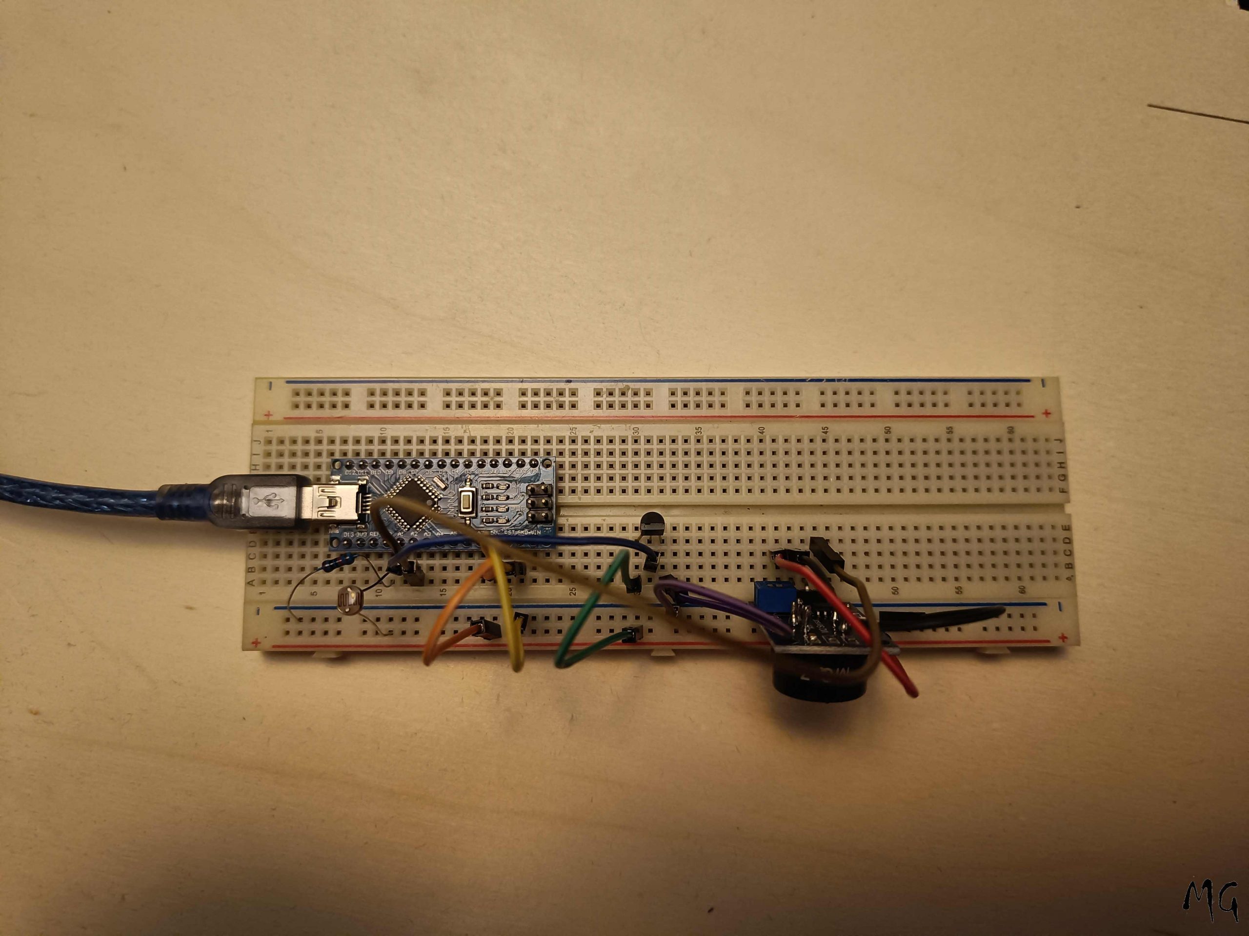
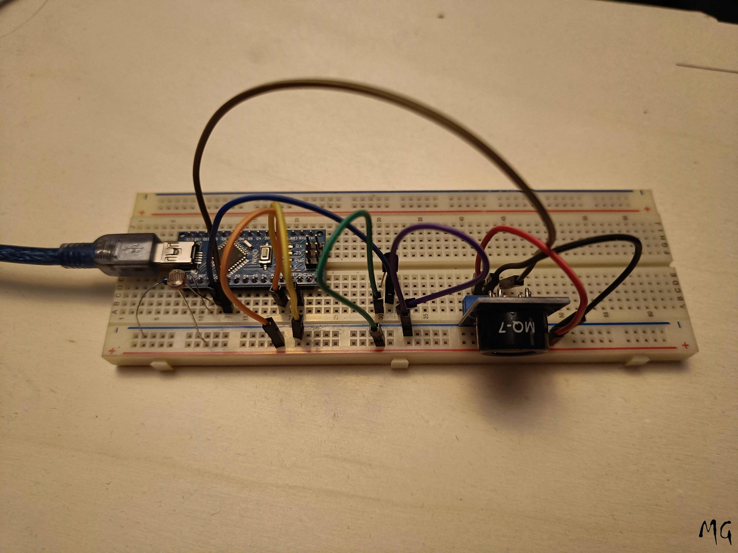
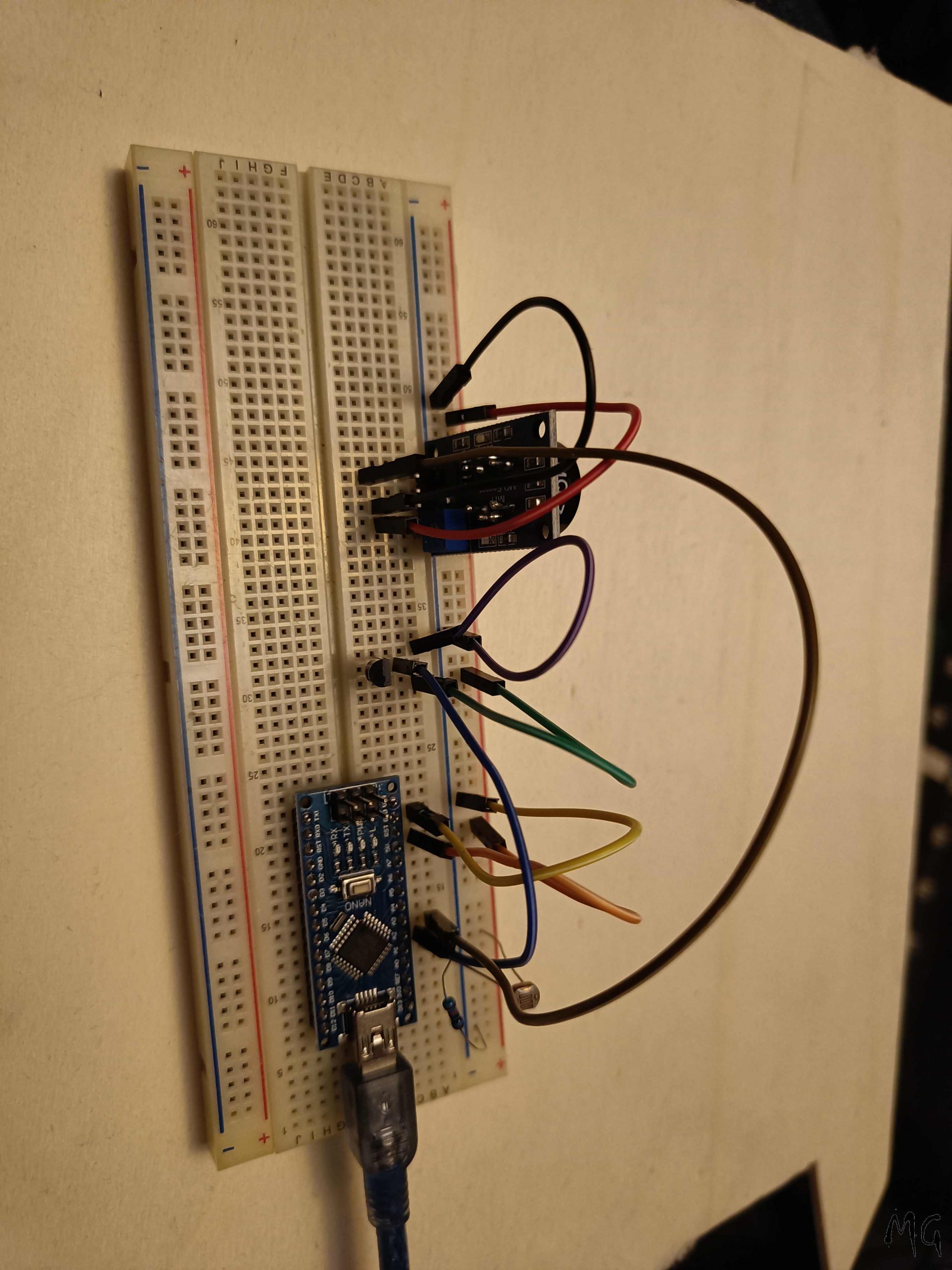
The initial design was created on a Breadboard / Prototyping board to prove the concept, during this testing, it was noted that because the MQ-7 has a high enough current draw that although it could be powered directly from the Arduino, it would affect the measurements of the other sensor. (see photos below). On the PCB design, it will need its own 5v supply.
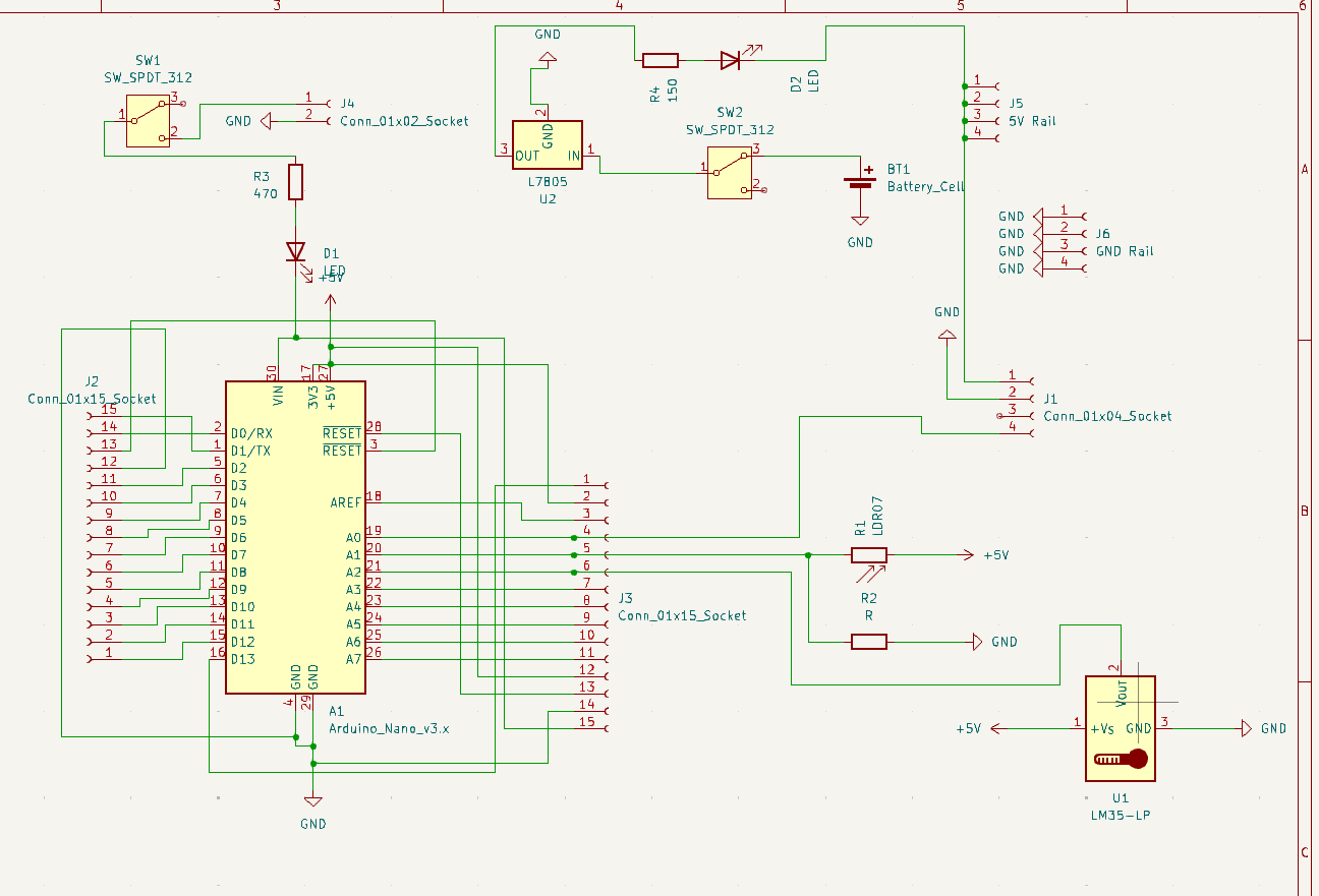
The Arduino code was compiled by using examples found on the internet on how to read each sensor individually.
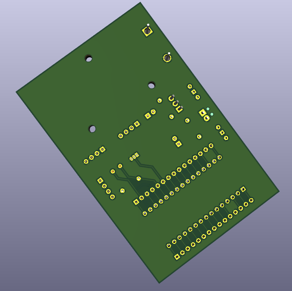
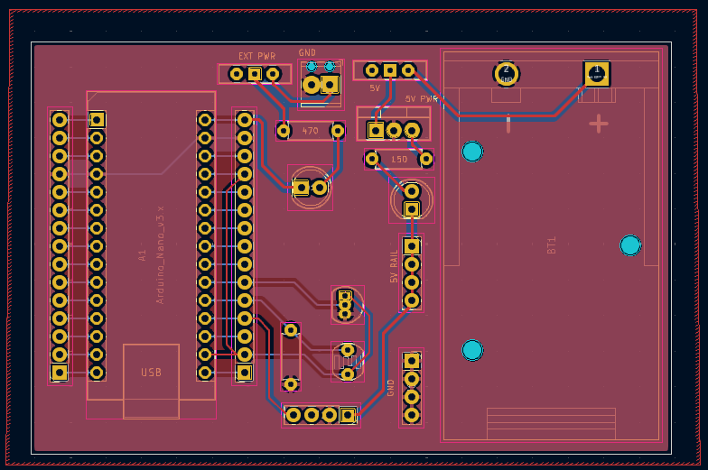
Using Kicad, i designed a PCB to have all of these sensors in situ, so not to waste the rest of the pins, additional headers were added so the other PINS could be used in the future, as well as adding 5v and GND rails.
The designs were sent out for manufacture by a 3rd Party.
Labview – Basics
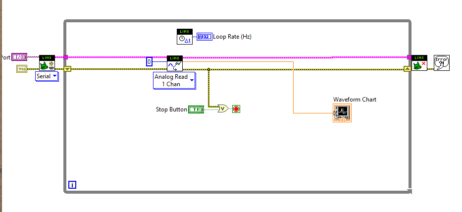
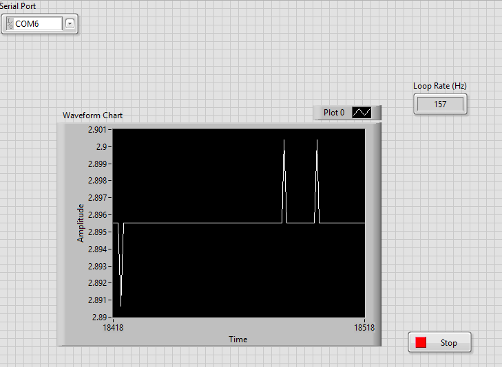
To get labview to work with the Arduino and use it as a “DAQ” , I use the tutorial on this YouTube video.
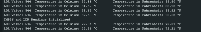
From there I used the included example sketch to make sure the programming worked, which it did. I then created a sketch based off of this to make sure the Program read the analogue input, in this case i used the LDR. In the images and video below you can see how this was done. The sample rate and graph are very high in the example as nothing was set. This will be improved in the future as this was a proof of concept.
Labview
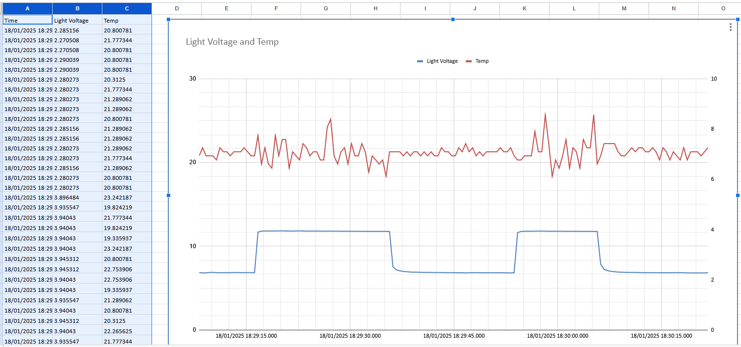
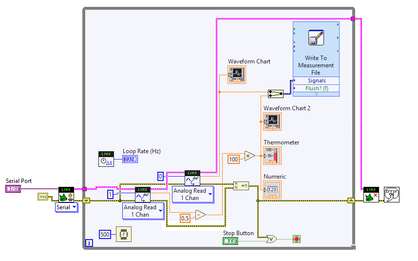
Below are a few imges of the Labview Program running with 2 senors and writing to a file. You will notice that the temp sensor becomes more irratic when there is high voltage on the light sensor, this could be because of a limitation of the arduino or how labview runs the program and reading the sensors sequentially.
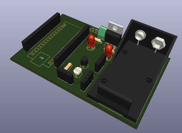
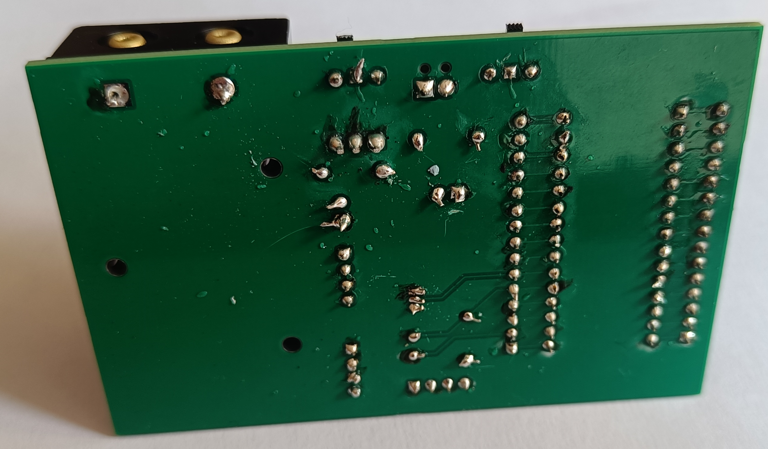
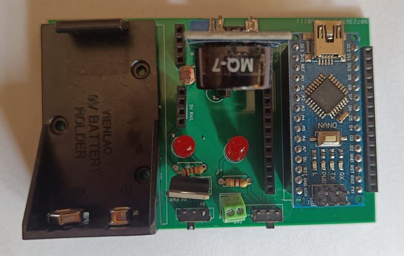
Soldering
Labview – Improvements and Conclusion
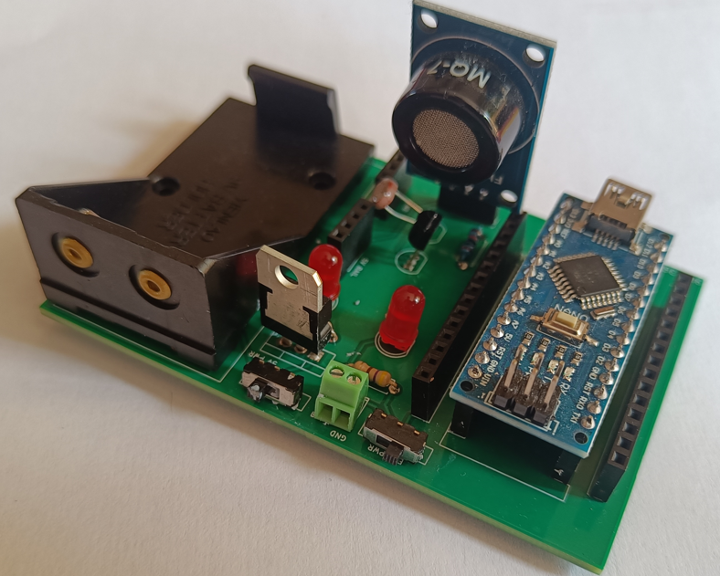
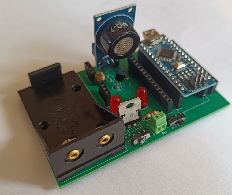
Below are pictures of the final and completed physical product. Something that i have noticed whilst making a few of these projects is that I need to label more of the PCB and what each switch , led and connection is and what it does.
In the future, the plan would be to create an .exe of the file so it could be run independently of Lavbiew.